Type and Model of Flow Meter

Measuring the flow of liquids is a critical need in many industrial plants. In some operations, the ability to conduct accurate flow measurements is so important that it can make the difference between making a profit or taking a loss. In other cases, inaccurate flow measurements or failure to take measurements can cause serious (or even disastrous) results.
With most liquid flow measurement instruments, the flow rate is determined inferential by measuring the liquid’s velocity or the change in kinetic energy. Velocity depends on the pressure differential that is forcing the liquid through a pipe or conduit. Because the pipe’s cross-sectional area is known and remains constant, the average velocity is an indication of the flow rate. The basic relationship for determining the liquid’s flow rate in such cases is:
Q = V x A
where
Q = liquid flow through the pipe
A = sectional area of the pipe
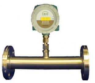
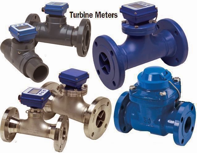
Turbine Flowmeter
Turbine meters have found widespread use for accurate liquid and gas measurement applications. The unit consists of a multiple-bladed rotor mounted with a pipe, perpendicular to the liquid flow. The rotor spins as the liquid passes through the blades. The rotational speed is a direct function of flow rate. Electrical pulses can be counted and totalized.
Features :
- Highly accurate and repeatible
- Eexcellent long-term reliability Installation flexibility
- Economic and cost-effective solution for applications requiring high accuracy
- Only one moving part reduces maintenance cost
- A wide selection of materials A wide selection of output options
- There is many different manufacturing design of turbine flow meters, but in general they are all based on the same simple principle:
- If a fluid moves through a pipe and acts on the vanes of a turbine, the turbine will start to spin and rotate. The rate of spin is measured to calculate the flow.
The turn down ratios may be more than 100:1 if the turbine meter is calibrated for a single fluid and used at constant conditions. Accuracy may be better than +/-0,1%.
Electromagnetic Flow meter
An electromagnetic flowmeter operate on Faraday’s law of electromagnetic induction that states that a voltage will be induced when a conductor moves through a magnetic field. The liquid serves as the conductor and the magnetic field is created by energized coils outside the flow tube.

The voltage produced is directly proportional to the flow rate. Two electrodes mounted in the pipe wall detect the voltage which is measured by a secondary element. Electromagnetic flowmeters can measure difficult and corrosive liquids and slurries, and they can measure flow in both directions with equal accuracy. Electromagnetic flowmeters have a relatively high power consumption and can only be used for electrical conductive fluids as water.
Ultrasonic Flow Meter
Ultrasonic flowmeters can be divided into Doppler meters and time-of-travel (or transit) meters.
Doppler meters measure the frequency shifts caused by liquid flow. Two transducers(one to transmit and the other to receive signal) are mounted in a case attached to one side of the pipe. A signal of known frequency is sent into the liquid to be measured. Solids, bubbles, or any discontinuity in the liquid, cause the pulse to be reflected to the receiver element, Fig. 10. Because the liquid causing the reflection is moving, the frequency of the returned pulse is shifted. The frequency shift is proportional to the liquid’s velocity.
A portable Doppler meter capable of being operated on AC power or from a rechargeable power pack has recently been developed. The sensing heads are simply clamped to the outside of the pipe, and the instrument is ready to be used. Total weight, including the case, is 22 lb. A set of 4 to 20 mA output terminals permits the unit to be connected to a strip chart recorder or other remote device.
Because solids particles or enterained gases are required for measurement, Doppler meters are not appropriate for clean liquids. In general, Doppler flow meters are less accurate than TOF flow meters, however, they are less expensive.
Time-of-travel(Transit-Time) meters have transducers mounted on each side of the pipe. The configuration is such that the sound waves traveling between the devices are at a 45 deg. angle to the direction of liquid flow. The speed of the signal traveling between the transducers increases or decreases with the direction of transmission and the velocity of the liquid being measured. A time-differential relationship proportional to the flow can be obtained by transmitting the signal alternately in both directions.
A limitation of time-of-travel meters is that the liquids being measured must be relatively free of entrained gas or solids to minimize signal scattering and absorption. (Back to Meter Types Table)
Positive-Displacement Flow meters
Although the positive-displacement flow meter market is slightly larger than it was in 2001, it has been essentially flat for the past 10 years. Today, the PD flow meter market is declining slightly. The main reasons the market is declining only slightly are the large installed base of PD meters, the large number of suppliers, and the ability of PD meters to measure high-viscosity liquids with high accuracy. PD meters are still widely used for downstream measurement of oil for custody transfer operations. Here they are being displaced by Coriolis meters, although they have a price advantage over Coriolis meters.
As the mechanism for the PD flow meters is simple, the PD flow meters has uncomplicated structure and parts, compared to the other flow meters. It was designed to contain little liquid contact parts so that liquid stays in the chamber very shortly. The PD flow meter driven by strong magnet coupling has gear system mounted outside measurement chamber, making it highly durable and easier to dismantle and assemble. As it does not contact liquid, it is highly durable and easy to dismantle and assemble.
Thermal Mass Flow Meter
Thermal Mass Flow Meter is the instrument of choice for reliable and accurate measurement of mass flows for various gases. It measures the mass flow of gas based on constant temperature differential technology and is able to measure gas flow in the range between 0 and 160 NMPS. Because neither temperature nor pressure measurement is required, MST series reduces installation cost and vastly improves system accuracy. The meter is easily installed or retrofitted with minimum downtime and provides superior, long-term process productivity and easy serviceability. MST series can have either inline sensor or insertion sensor. The inline sensor size ranges from 1” (25mm) to 12” (300mm) with either NPT thread connection or flange connection. The insertion sensors are available from 1” (25 mm) and above with the sensor mounting option of either compression fitting or flange. The indicator/transmitter provides a 4-20mA, pulse, RS- 485, HART, alarm, etc.
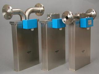
Coriolis Mass Flow meter
Coriolis Mass Flowmeter series is a mass flow meter that measures mass flow, density and temperature of liquids, slurries and gases. And it even measures oil content in water. It has no moving parts and doesn’t require any special device for installation. And it doesn’t require flow profile stabilization by means of flow straightener or straight pipe run either upstream or downstream. The wetted parts are made of high-grade stainless steel (SUS316L) and therefore can be used for corrosive liquids.

The mass flow-sensing element is composed of a pair of bent tubes, vibrators and displacement sensors. The trick here is to detect the Coriolis force applied on the tube by the flowing fluid inside the bent oscillating tube. In order to do that, the vibrators vibrate the bent tubes at the natural resonant frequency of the tubes. When there’s a flow inside the tubes, the Coriolis force at work distorts the vibration of the tubes. This distortion can be measured using the displacement sensors. The amount of distortion is directly proportional to the mass flow of the fluid inside the tube. By accurately processing the displacement, the accurate mass flow is directly measured. Liquids, slurries and gases can be measured. It boasts strong immunity to noise, high accuracy, wide turndown ratio, stability and reliability.