Kofloc Flow Meters For Gas Mixing Model RK120XM Series

Flow Meter  for Gas Mixing
MODEL RK120XM SERIES

The flow meter for
gas mixing uses a KOFLOC multiple flow meter to mix multicomponent fluids. Connection
of pipes to respective gas inlets and
the mixed gas outlet permit gases to be mixed. This flow meter is ideal for easy gas
mixing in laboratories and studies.

Features
• The simple
structure facilitates maintenance.

• The precision needle valve allows easy, fine
control of flow.


• All the parts are super-cleaned to ensure
excellent cleanliness.
• The flow meter is made into two- to
four-component types to handle    various gases in various flow ranges.

Standard Specifications
Fluids
Air,N2,O2,H2,He,Ar,CO2 (Calibration with
actual gas)
For other gases, please consult us regarding conversion conditions
or calibration with the actual gas to be used.
Flow range
From 5–50 ML/MIN to 1–10 L/MIN
10 L/MIN or less per line and 20 L/MIN or less in total
(Refer to the Capacity Table on page 55.)
Accuracy
FS ±2% (Measurement point)
* Optional: FS ±1% (Measurement point)
Proof pressure
0.5MPa
Available scale
10:1 * Optional 20:1
Material
SS
BS
Body block
SUS316
Brass
Tapered tube
Pyrex®,
glass
Packing
FKM
* Option (1)
NBR
Float
Pyrex,
SUS316, glass
Protective cover
Acrylic
resin
Temperature resistance
MAX60
Connection
Rc
1/4 (Standard), Rc 1/8 (Optional)


Ultrasonic Flow Meter jWAVE

Portable Ulrasonic Flow Meter
Ultrasonic Flow Meter jWAVE
Now you can capture accurate and reliable flow readings with your mobile device, with less hassle and in less time—wherever you need a flow or volume measurement.

No wires. No bulky electronics box to lug around. Your ultrasonic sensor hardware installs on the outside of your pipe in a snap—and senses through the pipe wall. Your mobile device displays readings and helps you set up the hardware.

And Bluetooth replaces the wires.
So you’ll get your job done more quickly, every time. What’s the jWAVE?
The jWAVE Flow Meter solution starts with the jWAVE App (downloadable from the app stores) and works on both iOS and Android devices.

The companion jWAVE Sensor is a compact, clamp-on ultrasonic transducer device that wirelessly transmits flow measurements. With a programmable controller, the output signal can be fed direct, with no other conditioning required.

The jWAVE is highly portable. Just bring the rechargeable clamp-on sensor in its lightweight, weatherproof case, along with a tablet or smartphone (iOS or Android). Bluetooth connectivity replaces wires, and the jWAVE App guides you through your application setup.

The convenient Cam Cleat lets you mount the sensor on any pipe in seconds—no cumbersome clamps required. Bi-directional readings are transmitted to your mobile device for display, and your location’s settings are stored in the jWAVE App, ready for reuse.

Now simply release the cleats, then take the compact sensor on to your next location.


SiteLab SL1188 Clamp On Ultrasonic Flow Meter

 SL1188 Industrial Non-Invasive Ultrasonic Transit-Time Flow Meter

GENERAL DESCRIPTION

The SL1188 Ultrasonic clamp on flow meters is a state-of-the-art universal transit-time flowmeter designed using SLSI technology and low voltage broadband  pulse  transmission.  While  principally  designed  for  clean  liquid  applications,  the  instrument  is  tolerant of liquids with small amounts of air bubbles or suspended solids found in most industrial environments.
The SiteLab SL1188 Flow meters is a state-of-the-art universal transit time Flow Meter for Heavy Industrial applications. Sophisticated electronics incorporating the latest developments in digital signal processing coupled with powerful ultrasonic transducers deliver highly accurate flow measurement for liquids in full pipes. While principally designed for clean liquid applications, the instrument is tolerant of liquids with a small quantity of air bubbles or suspended solids common in most industrial applications. 
The SL1188 ultrasonic clamp on flow meters offers low power consumption, high reliability, and outstanding applicability at an economical price. An easy to read display and clear, user-friendly menu selections make using the instrument simple and convenient. The instrument can be configured via keypad without any additional programming devices, is packaged in a die cast IP65 housing, and is available in your choice of non-invasive clamp-on or insertion transducer configurations.

The SL1188 ultrasonic flow meters features a self-contained 4-20 mA current loop signal output for instantaneous flow, as well as two independent temperature inputs for thermal energy monitoring. The instrument also features a 7 digit alpha- numeric display, parallel operation of positive, negative and net flow totalizers (with user-selectable scale factors) and configurable pulse and frequency outputs (transmitted via relay and open collector) for totalized flow.
As standard it incorporates a 1G SD Card for data logging and is supplied with the software to download stored data to your PC. installasi


Features :

  • Accuracy +/-0.5% of Reading 
  • Wide operating temperature range -40C to 150 C
  • One meter for a wide range of pipe sizes 25mm-5000mm
  • Clamp-on sensors are simple to install, leading to lower installation and labor costs
  • Clamp-on sensors mean no pipe cutting or process interruption and no plant shut-down
  • Wetted Sensors available for acoustically dead pipes.
  • Hygienic measurement, no risk of contamination, suitable for ultra clean liquids
  • Wide bi-directional Flow range of 0 to 12Metres/Second
  • Daily, monthly and yearly totalized flow 
  • Internally configured batch controller makes batch control convenient
  • Measurement is independent of fluid conductivity meaning a wider applicability than magnetic meters
  • 1G SD card high memory data logging, maximum memorize 512 days data.
  • Simple Menu driven setup with a wide range of common pipe materials, liners and fluids selectable.
  • Temperature inputs for energy measurement.  


SPECIFICATIONS

  •  Flow Range  : 0 to ±12 m/s 
  • Accuracy : ± 0.5 % of reading
  • Repeatability : ±0.3% of reading
  • Pipe Size : 25mm to 5000mm
  • Outputs :
    • Analog : 0/4 to 20mA (max load 75Ω)
    • Pulse output : 0 to 9999Hz, OCT, (min. and max. frequency is adjustable)
    • Relay output : SPST, max 1Hz, (IA@125VAC or 2A @ 30VDC)
    • Comms : RS232, RS485 Mod bus
  • Power Supply : 90 to 245 VAC, 48 to 63Hz. Or 10 to 36 VDC (both are standard)
  • Keypad : 16 (4×4) key with tactile action
  • Display : 40 character, 2 line (20×2) lattice alphanumeric, backlit LCD
  • Temperature : Transmitter:-40C to 60C
  • Transducer : -40C to 100C Standard. -40C to 150C High temp.
  • Humidity : Up to 99%RH, (non-condensing).
  • Physical Specifications :
    • Transmitter : IP65 Die-cast aluminum
    • Transducer : Encapsulated design Standard/maximum cable length : 9m/305Metres
    • Weight Transmitter : Approximately 4.7 lb (2.15kg) 
    • Transducer : 0.9kg (standard)

Explosion-proof enclosure (Optional) :

If going to place a sl1188 ultrasonic flow meters in an explosive atmosphere  (hazardous area), the ultrasonic flow meter’s explosion proof enclosure should be installed in a positively vented area. Before connecting the power supply, the user should create positive ventilation more than 5 times the enclosure volume for air exchange. The user must install the ultrasonic flow meters wiring in a safe area that  would not cause sparking or arcing due to short circuiting or wire breakage. Cables and wires should be installed through explosion-proof conduit. Explosion-proof threaded conduit unions should be used between the wired conduits, conduits and junction boxes. The available thread. engagement  into the fitting should be more than 5-6 threads. When flexible connections are needed, ex-proof flexible cable conduits can be used.

Material :Die-cast al uminum
Explosi on-proof rating : Exd Ⅱ BT4
Electrical   interface : 4×G1/2 ″
Wmm: 0.15
Ra:  3.2 
Installation Site Selection


When selecting a measurement site, it is important to select an area where the fluid flow profile is fully developed to guarantee a highly accurate measurement. Use the following guidelines to select a proper installation site:

  • Choose a section of pipe that is always full of liquid, such as a vertical pipe with flow in the upward direction or a full horizontal pipe.
  • Ensure enough straight  pipe length at least equal to the figure shown below for the upstream and down stream transducers installation.


Clamp-on Transducers Installation Methods 

Clamp-on Ultrasonic Flow meters are installed simply by applying coupling compound on the bottom of the transducers and strapping them to the outside of the pipe. SiteLab Clamp on Ultrasonic Flow meters are internationally known for their simple and convenient installation and low maintenance characteristics.

V method installation on pipe size :1” to16”(25mmto 400mm)

Flow Meter

Introduction to Flow Meters
What are Flow meters?
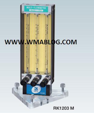
A flow meter is an instrument used to measure linear, nonlinear, mass or volumetric flow rate of a liquid or a gas.
Selecting a Flow Meter The basis of good flowmeter selection is a clear understanding of the requirements of the particular application. Therefore, time should be invested in fully evaluating the nature of the process fluid and of the overall installation. Here are some key questions which need to answered before selecting a flow meter:
What is the fluid being measured by the flowmeter or flowmeters (air,water,etc…)?
Do you require rate measurement and/or totalization from the flow meter?
If the liquid is not water, what viscosity is the liquid?
Is the fluid clean?
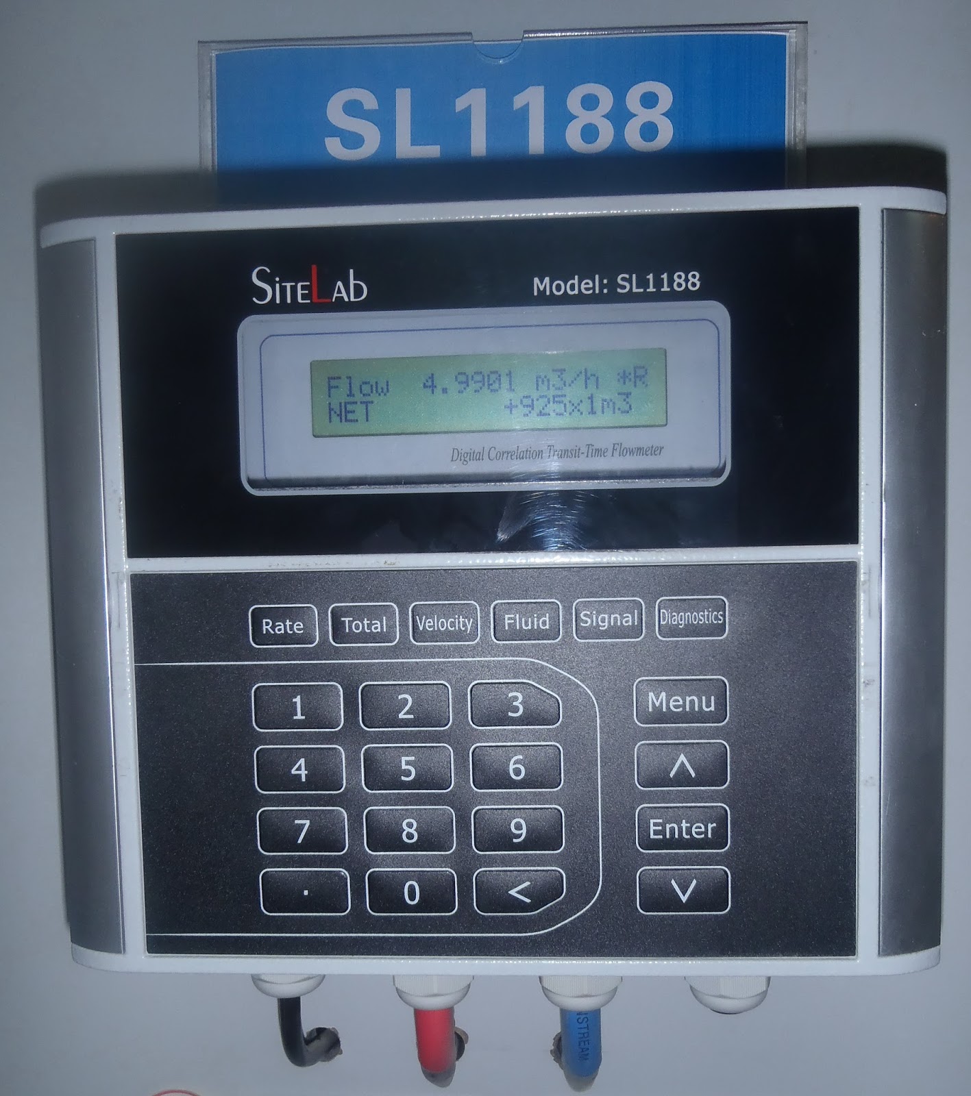
Do you require a local display on the flow meter or do you need an electronic signal output?
What is the minimum and maximum flow rate for the flow meter?
What is the minimum and maximum process pressure?
What is the minimum and maximum process temperature?
Is the fluid chemically compatible with the flowmeter wetted parts?
If this is a process application, what is the size of the pipe?
Flow Measurement Orientation
When choosing flowmeters, one should consider such intangible factors as familiarity of plant personnel, their experience with calibration and maintenance, spare parts availability, and mean time between failure history, etc., at the particular plant site. It is also recommended that the cost of the installation be computed only after taking these steps. One of the most common flow measurement mistakes is the reversal of this sequence: instead of selecting a sensor which will perform properly, an attempt is made to justify the use of a device because it is less expensive. Those “inexpensive” purchases can be the most costly installations.
The basis of good flow meter selection is a clear understanding of the requirements of the particular application. Therefore, time should be invested in fully evaluating the nature of the process fluid and of the overall installation.
The first step in flow sensor selection is to determine if the flowrate information should be continuous or totalized, and whether this information is needed locally or remotely. If remotely, should the transmission be analog, digital, or shared? And, if shared, what is the required (minimum) data-update frequency? Once these questions are answered, an evaluation of the properties and flow characteristics of the process fluid, and of the piping that will accommodate the flowmeter, should take place. In order to approach this task in a systematic manner, forms have been developed, requiring that the following types of data be filled in for each application: Click here to download the Flowmeter Evaluation Form
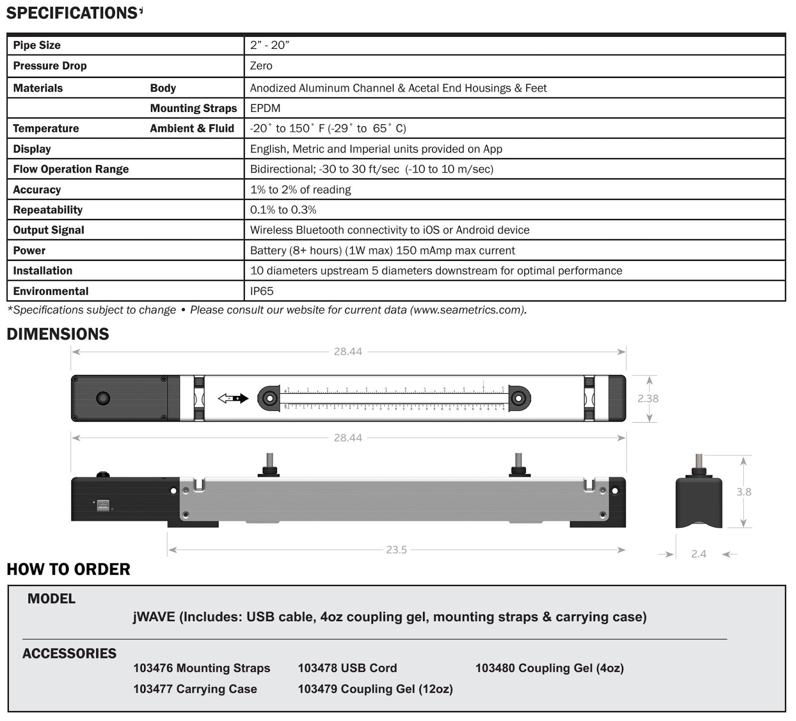
Fluid and flow characteristics: In this section of the table, the name of the fluid is given and its pressure, temperature, allowable pressure drop, density (or specific gravity), conductivity, viscosity (Newtonian or not?) and vapor pressure at maximum operating temperature are listed, together with an indication of how these properties might vary or interact. In addition, all safety or toxicity information should be provided, together with detailed data on the fluid’s composition, presence of bubbles, solids (abrasive or soft, size of particles, fibers), tendency to coat, and light transmission qualities (opaque, translucent or transparent?).
Expected minimum and maximum pressure and temperature values should be given in addition to the normal operating values when selecting flowmeters. Whether flow can reverse, whether it does not always fill the pipe, whether slug flow can develop (air-solids-liquid), whether aeration or pulsation is likely, whether sudden temperature changes can occur, or whether special precautions are needed during cleaning and maintenance, these facts, too, should be stated.
Concerning the piping and the area where the flowmeters are to be located, consider:
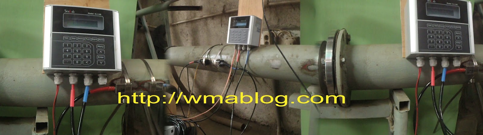
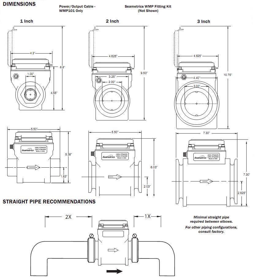
For the piping, its direction (avoid downward flow in liquid applications), size, material, schedule, flange-pressure rating, accessibility, up or downstream turns, valves, regulators, and available straight-pipe run lengths.
The specifying engineer must know if vibration or magnetic fields are present or possible in the area, if electric or pneumatic power is available, if the area is classified for explosion hazards, or if there are other special requirements such as compliance with sanitary or clean-in-place (CIP) regulations.
The next step is to determine the required meter range by identifying minimum and maximum flows (mass or volumetric) that will be measured. After that, the required flow measurement accuracy is determined. Typically accuracy is specified in percentage of actual reading (AR), in percentage of calibrated span (CS), or in percentage of full scale (FS) units. The accuracy requirements should be separately stated at minimum, normal, and maximum flow rates. Unless you know these requirements, your flowmeter’s performance may not be acceptable over its full range.
In applications where products are sold or purchased on the basis of a meter reading, absolute accuracy is critical. In other applications, repeatability may be more important than absolute accuracy. Therefore, it is advisable to establish separately the accuracy and repeatability requirements of each application and to state both in the specifications.
When a flowmeter’s accuracy is stated in % CS or % FS units, its absolute error will rise as the measured flow rate drops. If meter error is stated in % AR, the error in absolute terms stays the same at high or low flows. Because full scale (FS) is always a larger quantity than the calibrated span (CS), a sensor with a % FS performance will always have a larger error than one with the same % CS specification. Therefore, in order to compare all bids fairly, it is advisable to convert all quoted error statements into the same % AR units.
In well-prepared flow meter specifications, all accuracy statements are converted into uniform % AR units and these % AR requirements are specified separately for minimum, normal, and maximum flows. All flowmeters specifications and bids should clearly state both the accuracy and the repeatability of the meter at minimum, normal, and maximum flows.
If acceptable metering performance can be obtained from two different flow meter categories and one has no moving parts, select the one without moving parts. Moving parts are a potential source of problems, not only for the obvious reasons of wear, lubrication, and sensitivity to coating, but also because moving parts require clearance spaces that sometimes introduce “slippage” into the flow being measured. Even with well maintained and calibrated meters, this unmeasured flow varies with changes in fluid viscosity and temperature. Changes in temperature also change the internal dimensions of the meter and require compensation.
Furthermore, if one can obtain the same performance from both a full flowmeter and a point sensor, it is generally advisable to use the flowmeter. Because point sensors do not look at the full flow, they read accurately only if they are inserted to a depth where the flow velocity is the average of the velocity profile across the pipe. Even if this point is carefully determined at the time of calibration, it is not likely to remain unaltered, since velocity profiles change with flow rate, viscosity, temperature, and other factors.
Before specifying a flow meter, it is also advisable to determine whether the flow information will be more useful if presented in mass or volumetric units. When measuring the flow of compressible materials, volumetric flow is not very meaningful unless density (and sometimes also viscosity) is constant. When the velocity (volumetric flow) of incompressible liquids is measured, the presence of suspended bubbles will cause error; therefore, air and gas must be removed before the fluid reaches the meter. In other velocity sensors, pipe liners can cause problems (ultrasonic), or the meter may stop functioning if the Reynolds number is too low (in vortex shedding meters, RD > 20,000 is required).
In view of these considerations, mass flowmeters, which are insensitive to density, pressure and viscosity variations and are not affected by changes in the Reynolds number, should be kept in mind. Also underutilized in the chemical industry are the various flumes that can measure flow in partially full pipes and can pass large floating or settleable solids.

Alia Sanitary Flow Meter


Alia Flow Meter
Sanitary Flow Meter
Food Grade Flow Meter
Electromagnetic Flowmeter

AMF601 Series is a sanitary type electromagnetic Flowmeter ideal for conductive liquids. It comes in sizes from 25 to 100 mm.
The AMF601 is widely used for drink water, Milk , food & beverage juice and many other industrial fluid.
AMF601 Series electromagnetic flowmeter could be used in compact or separate model with AMC Series converter of electromagnetic Flowmeter.

FEATURES

  •  Light and compact version
  •  Flow Velocity range:0-12 m/s, with precisely measure for low flow applications 
  •  IDF Tri-Clamp or Union screw Connection
  •  It excellent for high pressure application
  •  Protection class: IP68 is available, and the sensor can sink into the water
  •  PTFE Liner is suit for vacuum tube
  •  High accuracy of +/-0.4% value of reading (or+/-0.2% value of reading)
  •  With Forward/Reverse flowrate measure function
SPECIFICATION

Size: Cable Entry:
25mm , 32mm, 40mm, 50mm PG11
65mm, 80mm, 100mm Ambient Temperature:
1″, 1-1/4″, 1-1/2″, 2″, 3″ , 4″

-25 to +60 oC
Measuring Range: Process Connection:
Velocity   0-0.25 m/s min. IDF Tri-Clamp
                0-12 m/s max. Union Screw
Material: Grounding Resistance:
Tube & Connection Must be  less then 10 
Stainless Steel 304 or 316 Accuracy:
Coil Housing +/-0.5% reading (Velocity>=0.5m/s)
Stainless Steel 304 (standard) +/-0.2% reading
Stainless Steel 316(Option) (Suit for AMC3100 Converter only)
Liner +/-0.0025 m/s (Velocity < 0.5 m/s)
PTFE Temperature:
Electrode
-40 to +150 oC
Stainless Steel 316L Max. Pressure:
Hastelloy B 10 Kg/cm2 (standard)
Hastelloy C 40 Kg/cm2(option)
Titanium Explosion Proof:
Tantalum Exd(ib)ibqIIBT5 
Tungsten Carbide (with AMC3100 only)


Platinum
Protection:
IP 68
IP68(Submersible)
Conductivity:
More than 5 uS/cm

Alia Ultrasonic Flow Meter

Portable flow meter
Clamp On Ultrasonic Flow meter
Hand Held Ultrasonic FLow Meters

Ultrasonic Flowmeter

AUF610series is a portable transit-time ultrasonic flowmeter with clamp-on transducers for non

AUF610series AUF610series is a Alia portable transit-time ultrasonic flowmeter with clamp-on transducers for non-invasive liquid measurement.
AUF750 Series
AUF750 series is a fixed mounted, transit-time ultrasonic Flowmeter, with clamp-on transducers for non-invasive liquid measurement. Our microprocessor based, user friendly, field …
AUF760 Series
ALIASONIC AUF760 series is a Alia fixed mounted, transit-time ultrasonic flowmeter, flange end transducers for non-invasive liquid measurement. Our microprocessor based, user friendly …
AUF600 Series
ALIASONIC AUF600 series is a Alia portable transit-time ultrasonic flowmeter with clamp-on transducers for non-invasive liquid measurement. Based on microprocessor and programmable f …

Non Metal Electromagnetic Flow meter


WMP-Series
Plastic-Bodied Magmeter
Electromagnetic Flow Meter
Seametrics Flow Meters


FEATURES
• No moving parts
• Minimal straight pipe required
• Battery powered
• Built-in rate & total indicator
• Corrosion resistant
• Pulse output (WMP101 only)

APPLICATIONS
Usage monitoring, such as:
• Industrial wastewater discharge
• Grey water
• Well monitoring
• Irrigation

GENERAL INFORMATION

The WMP-Series flow meters is a full-bore, plastic-bodied electromagnetic flow meters designed for flow and usage monitoring applications in 1, 2 and 3 inch pipe.  The polypropylene flow tube offers cor-rosion resistance to a wide range of chemicals and fertilizers. It is light weight and easy to install or remove from the pipe for inspection*.With no moving parts, the magmeter permits unobstructed flow, minimizing flow disturbances and straight pipe requirements. The WMP-Series flow meters can be used in piping configurations where there is little space between the meter and an elbow or valve. The WMP-Series flow meters is resistant to wear from sand and debris found in ground or surface water.  Since there are no bearings or pro-peller to wear out, maintenance and repair costs are kept to a minimum and it tolerates high flows without damage.A hinged polyethylene cover is included that protects from dust and UV rays, while permitting easy access to the flow rate and total display. The electronics housing can be fitted with cross-drilled screws and seal wire for tamper-evidence.  Flow rate and total can be displayed in a variety of units, customer-selected and factory-set.

The WMP-Series flow meters is used for tracking flow rate and total flow in usage monitoring applications including wells, industrial waste-water, heap leach mining discharge, cooling tower deduct, turf, landscape, and other water reclamation applications. In the event of DC power loss, or when changing batteries, the WMP will retain internal settings and flow total.The  WMP101 flow meters is externally powered via a 5-pin connector cable (20ft/6m) which also provides pulse output for use with a variety of Seametrics and other displays and controls for remote reading, data logging, pulse-to-analog conversion, and telemetry applications.The WMP104 flow meters is a battery-operated unit for use when pulse output is not required. The standard batteries are user replaceable with an approximate 1-2 year life depending on usage. An extended battery life option offers an estimated 2-4 year life depending on usage.*Includes Seametrics NPT fitting kit on 2” and 3” models.


Water leaks Detection

Ultrasonic flow meters FLOMIC FL5034 and FL5054

Solution for water leaks detectionultrasonic flow meter FL 5034 5054: Solution for water leaks detection

The battery-powered FLOMIC FL5034 and FL5054ultrasonic flow meters are intended for operational and invoicing measurements of instantaneous flow rate,pressure and consumption in water piping in observance of standard EN 14154 in water works, water distribution systems and other industrial applications.
The features of the FLOMIC flow meters make them suitable for water-leak detection and tracking and monitoring of the general condition of water-supply networks.

Ultrasonic flow meter FL 50X4 design

These flow meters are of a compact design with the IP 68 protection class. They are characterised by high measurement accuracy and long-term stability over a wide range of measured values. The meters do not need any external power supply, do not include any moving parts and, have significantly lower hydraulic losses. 
The measurement method utilised by these meters is a single-beam (FL5034) or dual-beam (FL5054) transit-time pulse method based on evaluation of the time needed for an ultrasonic signal to cross the distance between two measuring transductors. In the standard version, the meter measures instantaneous flow rate (in m3/hour) and the total volume of water passed through the meter (in m3) in the given flow direction.
The measured data are converted into passive pulse output signals. The meter output signals can be connected via data transfer systems to remote computer control stations. Flowmeter electronics also includes data storage with various possibility to connect (GSM module, RS232, optical data probe). This feature can be usefull for distance measuring points without electricity.
Flow meters FLOMIC FL 50X4 can effectively save customers costs everywhere, where needs to measure water and is not possible or is expensive to connect to emergy power grid.

Technical parameters

usage measurement of total volume of the water passed through and instantaneous flow rate and pressure
the principle of the measurement transit-time
type – one beam (1B – FL5034) or dual beam  (2B – FL5054)
– compact version
the range of dimensions DN32 to DN300
temperature of measured fluid to 50°C
pressure up to 4.0 MPa
flow sampling period 1 sec
electrical outputs pulse and current
interface optical probe, RS 232, GSM module
data storage data archive
power source Li battery 3.6V, 16Ah, lifetime 6 to 8 years
protection class IP68

Ultrasonic flow meters FLOMIC FL103X

Ultrasonic flow meters FLOMIC FL103X

Ultrasonic flow meters FLOMIC FL103X
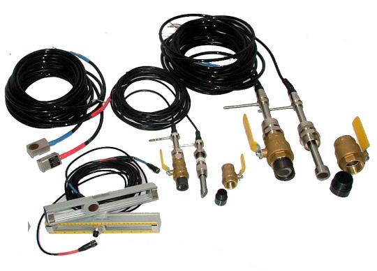
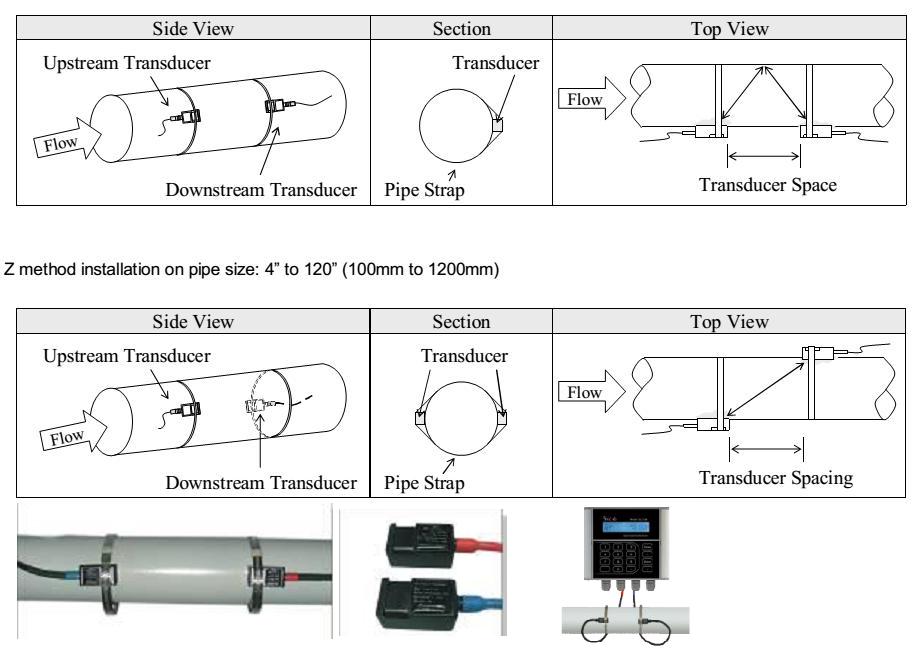
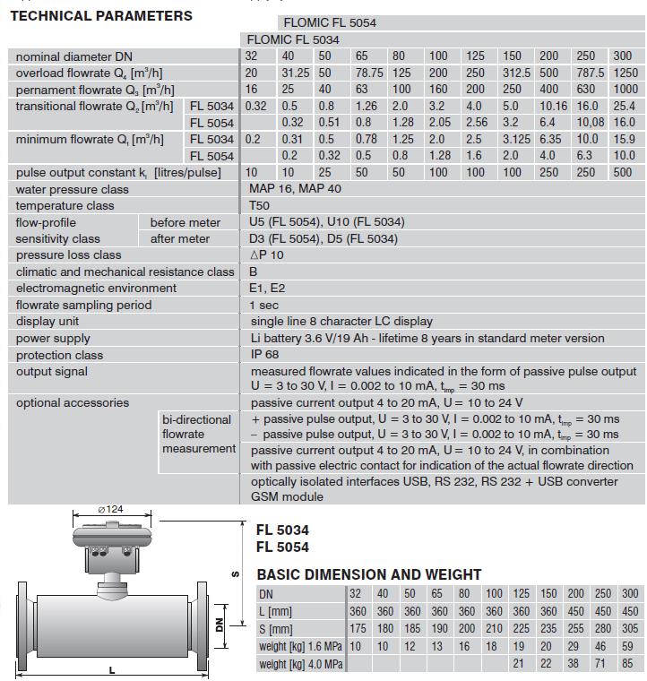
Ultrasonic flow meters of the type series FLOMIC FL103X (FL1034 – the compact version, FL1035 – with remote electronic unit) are intended for measurement and storage of the measured data of instantaneous flow rate, total volume passed through the meter sensor, of cold and hot water and other liquids of similar properties in a wide range of industrial applications. Optionally, the meters can be provided with pressure gauges to monitor the fluid pressure in the piping.
The FLOMIC FL103X meters are noted for high measurement accuracy and long-term stability over a wide range of measured values. They have equipped by internal battery and they can be installed anywhere without availability of external power. The meters include no movable parts and, compared to conventional flow meters, their hydraulic losses are significantly lower.
The associated electronic unit provides for processing of the sensor signals and visualisation of the values of instantaneous flow rate, total fluid volume passed through the meter sensor and fluid pressure, as well as for archiving of the measured data in specified time intervals in the internal meter memory unit. The archived data can be retrieved either via an optical interface, RS 232 communication line or GSM module for further processing by, for example, a notebook computer. On-line processing of the measured values is also possible using the pulse or current (4 to 20mA) outputs.

Technical parameters:

usage measurement of total volume of the liquid passed through, instantaneous flow rate and pressure
the principle of the measurement transit-time
type – one beam (1B)
– remote and compact version
rated piping size DN32 to DN300
maximum permitted pressure 1.6 MPa, 4 MPa (classes MAP 16 and MAP 40)
measurement accuracy according to EN 14154
flow sampling period 1 sec
tempetarure of liquid up to 150°C
protection class IP67 / IP68 in remote version
power source Li battery 3.6V/16Ah, garanted battery lifetime 6 to 8 years

Ultrasonic Flow Meters

Ultrasonic flow meters

Ultrasonic flow metersUltrasonic flow meters have been designed for industrial application where they can measure flow rate of a wide range of liquid media, whether electrically conductive or not, including specific corrosive liquids. The scope of application for ultrasonic flow meters covers many functions in practically all industry lines.
In ultrasonic flow meters, the flow rate values are determined from the difference between the travel times of ultrasonic waves propagating in the measured liquid in and against the flow direction.
Ultrasonic flow meters are noted for high accuracy, excellent long-term stability of measurement over a wide range of measured values, low hydraulic losses and simple maintenance. Ultrasonic flow meters are supplied in optional configurations according to the customer requirements, for a wide range of piping sizes. The associated electronic control unit supplies power to the ultrasonic probes, processes the sensor signals and shows the measured values on the meter display. The measured values are also available at optional electric signal outputs.

Main advantages:

  • high measurement accuracy 
  • long-term measurement stability over a wide range of measured values
  • high operational reliability and practically no maintenance requirements
  • extra-low hydraulic losses 
  • optional long-distance transfer of measured data
Model of Ultrasonic Flow Meters :